
CUTTING
CHARACTERISTICS
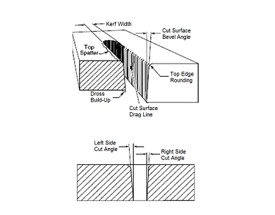
Cut SurfaceThe cut surface is influenced by process and positioner precision more than by other parameters.
Top edge rounding
Caused by the heat of the plasma arc at the top surface of the cut. Proper torch height control can minimize or eliminate top edge rounding. Excessive top edge rounding is often a sign that torch cutting height should be lower.
Top spatter
Top spatter is caused by fast cutting or by too high a torch height setting. Reducing cut speed or lowering torch cutting height will reduce top spatter. Top spatter is easy to remove.
Bottom dross
Molten metal may build up on the bottom of the plate. Faster cut speeds reduce bottom dross as less material is melted. Bottom dross that is easy to remove is an indication of slow cutting speed. Bottom dross that is difficult to remove or requires grinding is an indication of too fast cut speed.
Kerf
Kerf is the width of the cut removed by the plasma arc. Kerf is very important to the accuracy of a work piece cut to specific dimension. The rule of thumb for estimating the kerf in DAC (digital to analog convertor) is it will be about one half to two times wider than the diameter of the nozzle orifice. Factors that affect kerf are nozzle size, cutting speed, amperage setting and standoff distance.
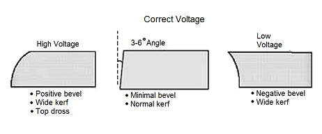
Bevel angle
Precision cut processes produce bevel angle in the 0-3° range. Conventional plasma cutting will produce larger bevel angles. Proper torch height control will produce the smallest bevel angle, as well as improved kerf width and minimal top edge rounding. A slower cut speed can be used when cutting circles and corners to reduce bevel.
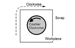
Direction of cut – The plasma has a clockwise swirl as it exits the torch tip. Considering the direction of torch travel, the right side of the cut will always show less bevel and top edge rounding than the left side. Program cuts so that the right side will be on the finished part and the left side will be scrap.
Nitride contamination – Air plasma cutting will produce nitride contamination of the cut face on carbon steel and stainless steel. Nitride contaminated surfaces will require grinding before welding to eliminate weld porosity. The depth of the contamination will be close to the Heat Affected Zone, between .005 and .010" in depth. Nitride contamination can be eliminated by using a process other than air plasma; oxygen plasma for carbon steel, H35 or nitrogen/WMS for non-ferrous materials.
Cut speed – Cut charts specify a cut speed that will produce high quality cut performance. Any plasma system can cut at faster or slower speeds, but cut performance will be affected. Cut speed should be reduced for corners and tight curves to reduce bevel and corner rounding.
Optimum cut speeds produce a trailing arc which will be visible in the slight arc lines visible in the cut face. Arc lines are useful for evaluating cut speed on mild steel, but less so for aluminum and stainless steel. Arc lines that trail at less than 15° indicate that cut speed is in the optimum range when air or oxygen plasma processes are used. Optimum cut quality in precision cutting processes will result in arc lines that are near vertical. A slow cut speed may show arc lines that angle forward and a fast cut speed will show arc lines at a sharper angle relative to the top of the plate.